
The Propulsion subsystem is in control of the rocket’s propulsion system. It is therefore involved in the development of code for simulating both the motor’s as well as the rocket’s performance, the manufacturing of solid propellant, and, lastly, the design and manufacturing of rocket motors.

In the pursuit of reaching a given altitude with great accuracy, the need of having the optimal motor emerged. This led to the development of a Matlab-based optimization tool with a Graphical User Interface (GUI) implementation. This tool combines the rocket’s flight performance with the performance of many different motors, to select the optimal one corresponding to the rocket’s requirements. In addition, the sub-system has developed a code to design and optimize the motor nozzle. This is achieved in conjunction with the computational study of the combustion of the solid propellant, during which the necessary data for the dimensioning of the nozzle is obtained. The aim is to maximize its performance, while also minimizing its weight. A further study of this is carried out using a CFD commercial code.
The subsystem has so far acquired technical expertise regarding the manufacturing procedure of solid propellants used in its motors. The fuel used is potassium nitrate and sorbitol (in a ratio of 65-35) as it has been experimentally found that this is the maximum efficiency for these substances. A significant factor ensuring the motor’s optimal performance is its proper construction. Bubbles and cracks should be avoided so as to achieve smooth surfaces. That’s the reason why specific stirring equipment has been constructed to achieve a proper homogenization of the oxidizer with the fuel, before and during its heating process, and introduced into the mold for the manufacturing of the grains. Grains are made of materials that offer the necessary support and protection to the fuel, while not affecting the efficiency of combustion. Another factor is the experimental study of its combustion. In particular, several propellant experiments have been carried out in parallel with the static tests of the motors carried out by the team to find and address possible problems to carry out a complete optimization of the process. As a result, useful data is obtained for the design of future motors, such as the effect of pressure on the propellant burning rate. The team manufactures igniters to start the motor. Their goal is immediate ignition with the help of guided sparks caused by pyrogen.
So far, the subsystem has successfully designed and built a Class G solid propellant motor. With the experience gained from the static testing of this motor and its use in Rocketry Project’s H1 and H2 rocket launches, the subsystem moved to the design of an I-Class SRM aiming to specific thrust profile.
The I-class motor has been tested from June 2021 until now aiming to obtain thrust and temperature data. Every single static test offers a great experience to the members of the Propulsion subsystem regarding the procedures of the assembly, the ignition and the final performance.
The aforementioned information is of great significance and has been taken into consideration during the design of an M-Class SRM,named Sirius. Sirius will be the first SRAD SRM to be hosted in a greek High-Power Rocket, something which is a great milestone for the entire greek experimental rocketry community. The motor has a It of 9750Ns and a MEOP of 6.5MPa.
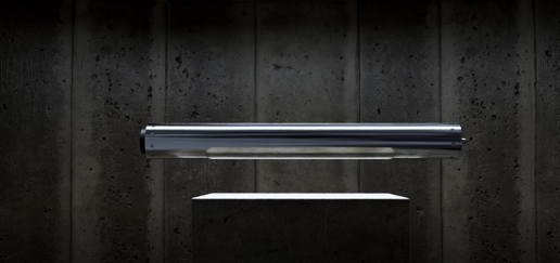
The design process that has been followed is based on the motor’s performance calculation, the design of each mechanical component, the optimization through thermostructural analysis and flow analysis. Subsequently, a high criticality appears to the material selection as aerospace aluminum alloys and a fine graphite for the nozzle. Through this kind of procedure, the dimensioning of the motor has emerged and orders have been settled. The validation of the theoretical study is obtained through catastrophic strength tests at the motor’s components.
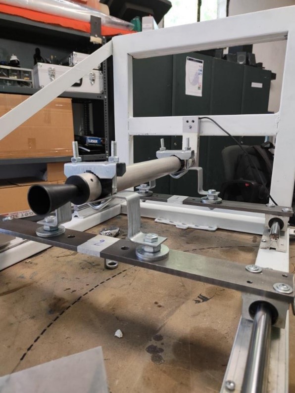
In combination with the motor’s design, the corresponding mechanical and electronic design of the testing structures was in progress regarding the procedures of the propellant production and the static tests of the SRM. For the propellant production, mechanical molds have been designed where the injection of the fluid propellant takes place and it is exposed to vibration and vacuum for air bubbles degassing. Regarding the static tests, three kinds of sensors are used: load cell for thrust, pyrometer for temperature and pressure transducer for pressure measurements. Lastly, the structure offers the team the chance to test the motor both horizontally and vertically, extracting the mass flow rate.

The motor’s electronics are researched and designed to achieve accurate measurements through our sensors and validate the motor’s functionality. The Printed Circuit Board (PCB) houses ICs such as an instrumentation amplifier, which amplifies a sensor’s output, or a current loop receiver, that converts a current output to voltage. Furthermore, the analog signals are digitized by ADC ICs and then transmitted to an MCU (Microcontroller Unit). Our team uses STM32 MCUs, which are coded in C programming language.